


AF-2

Pneumatic basics
Learn how pneumatic filter regulators remove condensed water and particles, stabilize compressed-air pressure, and how to compare port size, thread type, airflow, filtration, and drain options.
Compressed air is widely used to power air tools, cylinders, valves, spray equipment, packaging machines, assembly systems, and industrial automation. However, air coming directly from a compressor is not always ready for use. It may contain condensed water, dust, rust particles, pipe contamination, and unstable pressure. These conditions can reduce equipment performance and increase maintenance requirements. A pneumatic filter regulator combines air filtration and pressure regulation in one compact unit. It removes condensed liquid water and solid particles while reducing the incoming air pressure to a more suitable and stable operating level. This guide explains how a filter regulator works, how its port and thread sizes should be understood, and what to check before selecting one for your pneumatic system.
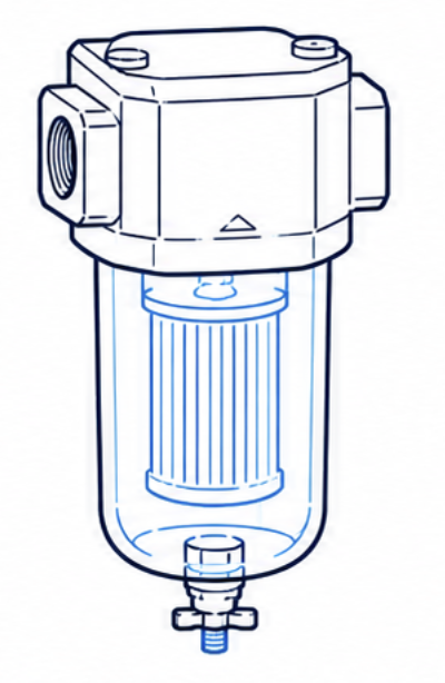
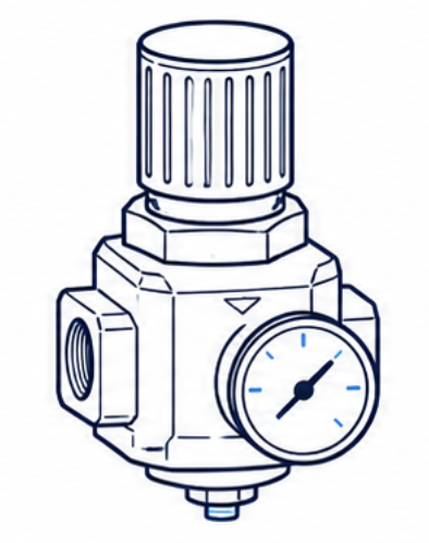
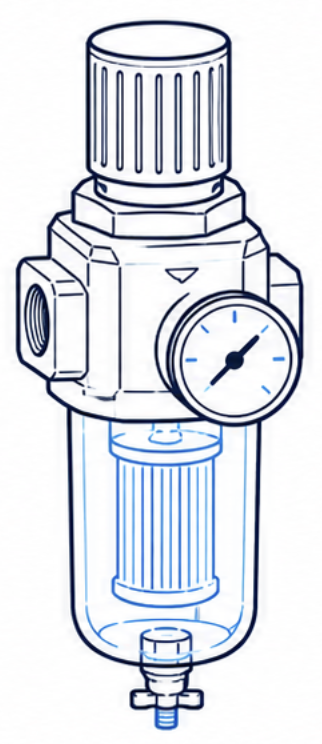
A pneumatic filter regulator combines two air-preparation functions:
Because these two functions are integrated into one body, a filter regulator generally requires less installation space and fewer pipe connections than a separate filter and regulator. Filter regulators are commonly used with:
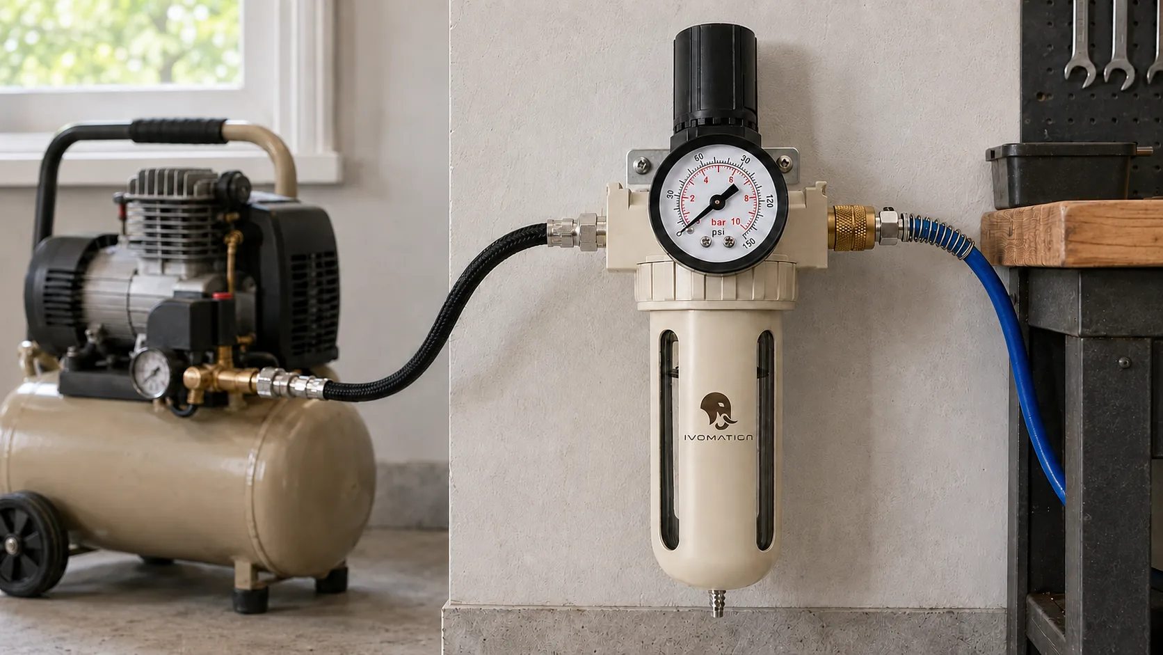
A filter regulator is often installed near the compressor outlet, at the entrance to a machine, or close to the pneumatic equipment it protects.
Compressed air may look clean, but it can contain several forms of contamination. Ambient air naturally contains moisture. When the compressor pressurizes the air and the air later cools inside a receiver tank or pipeline, part of that moisture can condense into liquid water. The compressed-air system may also contain:
Without appropriate air treatment, these contaminants may contribute to:
The pressure supplied by a compressor is also often higher than the pressure required by the downstream equipment. A regulator reduces this supply pressure and helps maintain a more stable outlet pressure during operation.
The basic operating process can be divided into filtration, water separation, drainage, and pressure regulation.
Compressed air enters through the inlet port. Inside the filter section, the airflow is redirected or rotated. This change in direction helps heavier water droplets and larger particles separate from the moving air.
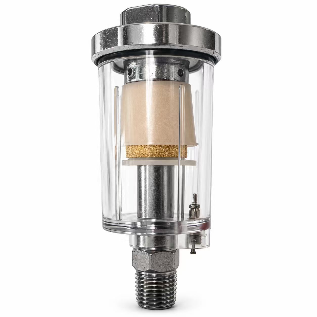
Separated liquid collects inside the filter bowl. The air then passes through a filter element, which captures solid particles according to the element’s filtration rating. The collected water can be removed through a:
After filtration, the air enters the pressure-regulation section. The regulator uses an adjustment mechanism, spring, diaphragm or piston, and internal valve structure to control outlet pressure. The operator turns or lifts and turns the regulator knob to select the required downstream pressure.
The treated air exits through the outlet port and flows toward the connected tool, valve, cylinder, or machine. Most filter regulators include either a pressure gauge or a gauge connection so the outlet pressure can be monitored.
These air-preparation products have different functions. | Product | Main Function | | --- | --- | | Air filter | Removes condensed water and solid particles | | Air regulator | Reduces and controls outlet pressure | | Filter regulator | Combines filtration and pressure regulation | | Lubricator | Adds a controlled amount of oil mist to the downstream air | | FRL unit | Combines filter, regulator, and lubricator | FRL stands for Filter, Regulator, and Lubricator. A complete FRL unit is useful when the downstream equipment requires filtered air, controlled pressure, and additional lubrication. However, not every pneumatic application should use a lubricator. Many modern valves, cylinders, and tools are pre-lubricated or designed to operate without continuous oil mist. A filter regulator is often the better choice when the system needs cleaner, controlled air but does not require additional lubrication.
A suitable filter regulator should be selected according to the actual pneumatic application rather than appearance or price alone. A practical selection order is:
Airflow is one of the most important selection factors. The filter regulator must supply enough compressed air for all downstream equipment that may operate at the same time. If the unit is too small, the pressure gauge may show the correct pressure while the equipment is stopped. However, when the equipment begins consuming air, the outlet pressure may fall sharply. Insufficient airflow can cause:
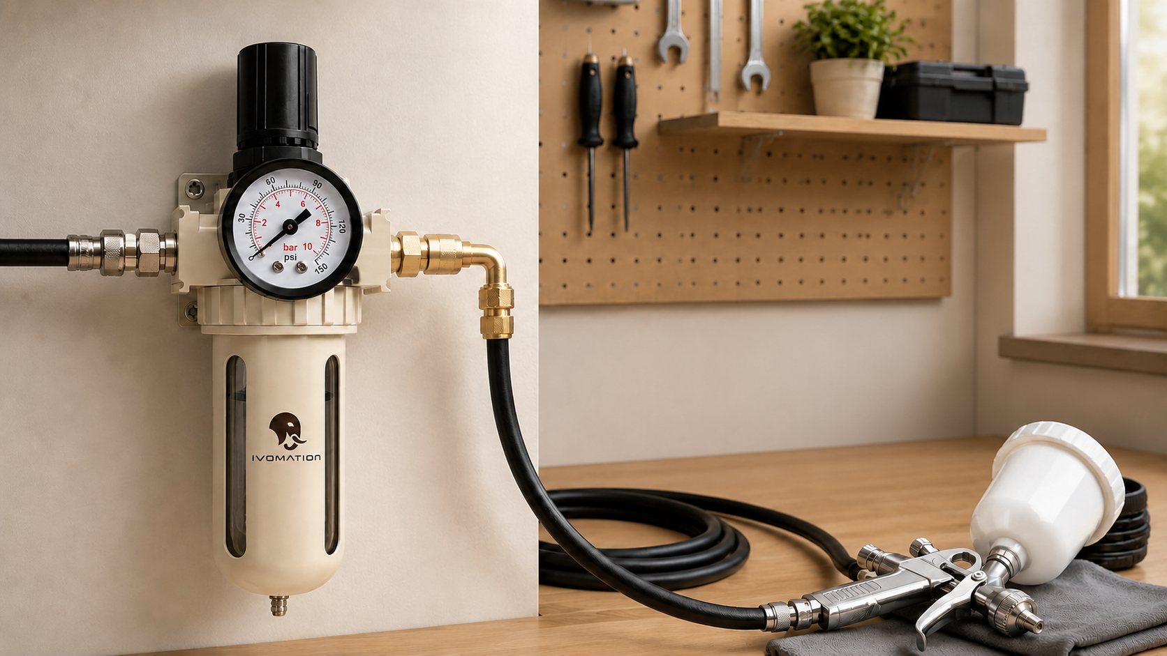
For example, a regulator may show 6 bar while the spray gun is idle, but fall to a much lower pressure when spraying begins. This does not always mean the regulator is defective. The cause may be:
Always compare the product’s rated airflow with the equipment’s actual air-consumption requirement. Where possible, allow some extra flow capacity rather than selecting a unit that operates continuously at its maximum rating.
Common pneumatic filter-regulator port sizes include:
A compact 1/4-inch filter regulator is commonly used with small compressors, spray guns, nail guns, and compact pneumatic tools. Larger ports are often used for equipment or systems requiring greater airflow. However, port size does not directly tell you the product’s actual airflow capacity.
The marked size is normally a nominal pipe-thread size. It does not mean:
For example, a filter regulator may have a 1/4-inch threaded port, while the push-to-connect fitting installed in that port may be designed for 8 mm tubing. These are three different measurements:
They must be checked separately.
Two filter regulators with the same 1/4-inch port size may have very different rated airflow. Flow capacity is also affected by:
A larger port does not automatically guarantee better performance, and a smaller port does not automatically mean the product is unsuitable. The correct method is to compare:
Port size is important for connection compatibility, but flow data is more important for performance.
Common pneumatic thread markings include:
These markings are related, but they should not all be treated as identical.
G threads are generally parallel pipe threads and are commonly associated with BSPP. The thread diameter remains parallel along its length. These connections often rely on:
The thread itself may provide mechanical engagement, while a separate sealing feature prevents leakage.
R commonly refers to a tapered external pipe thread in the BSP thread family. The thread becomes gradually narrower along its length. Tapered threads normally seal through thread engagement together with a suitable thread sealant.
PT is a marking still commonly seen in parts of Asia. It is often used for tapered pipe-thread connections, but suppliers may use the term differently. The exact thread specification should therefore be confirmed before ordering.
NPT is a tapered pipe-thread standard widely used in North America. NPT and BSP threads may have similar nominal size descriptions, but their thread angle, pitch, and geometry can differ. A fitting may appear to screw into the wrong port for one or two turns. This does not mean the connection is correct, reliable, or safe. Using mismatched threads may cause:
Always confirm both the nominal size and the thread standard. For example:
These should not be treated as automatically interchangeable.
Several pressure specifications may appear on a product datasheet.
This is the highest permitted pressure entering the product. The compressor or upstream system must remain below this limit.
This is the maximum pressure permitted during normal product operation. It should not be confused with a temporary test pressure or destructive-test result.
This is the pressure range that the regulator is designed to control. The required downstream pressure must fall inside this range. For example, a tool requiring 6 bar should be paired with a regulator that can maintain approximately 6 bar under actual airflow conditions.
Static pressure is the pressure shown when the downstream equipment is not consuming air. Working pressure, or dynamic pressure, is the pressure available while the tool or machine is operating. For the most accurate setting, adjust the regulator while the downstream equipment is consuming air. This helps reveal pressure loss caused by insufficient airflow, restrictive tubing, small fittings, or compressor limitations.
The filtration rating describes the approximate particle size that the filter element is designed to capture. Common ratings include:
Often used for basic particulate filtration and general air-tool applications.
Common for general pneumatic equipment, workshop use, regulators, valves, and standard industrial systems.
Used where finer particle control is required. It may be appropriate for more sensitive valves, instruments, or equipment, depending on the manufacturer’s requirements. A smaller micron rating is not automatically better. Finer filtration may:
A standard particulate filter also does not necessarily remove fine oil aerosols or water vapour. Applications requiring higher air quality may need additional treatment such as:
Select the filtration rating according to the downstream equipment and the required compressed-air quality.
The filter bowl collects separated liquid and contamination. That liquid must be removed before the bowl becomes overfilled.
A manual drain is opened by the operator. It is simple and commonly used in:
A semi-automatic drain releases collected liquid under certain pressure conditions, depending on its design. It can reduce manual drainage requirements but should still be inspected regularly.
An automatic drain removes collected liquid without routine manual operation. It is often preferred for:
Drain terminology may vary between manufacturers, so the operating method should be confirmed before purchase.
Not every regulator responds in exactly the same way. One useful distinction is between relieving and non-relieving regulators.
When the pressure setting is reduced, a relieving regulator can release some excess downstream pressure through the regulator. This is useful in many general pneumatic applications. However, the relieving function should not be treated as a replacement for a certified safety-relief valve.
A non-relieving regulator does not actively vent downstream pressure when the setting is reduced. The downstream pressure falls only when:
The correct type depends on the equipment and safety requirements.
Common filter-bowl constructions include:
A transparent bowl allows the user to see:
However, transparent polymer bowls may be affected by certain solvents, chemicals, cleaning agents, excessive heat, ultraviolet exposure, or pressures outside their rating.
A metal guard provides additional impact protection while retaining a visible inspection area. It is often suitable for workshop and industrial environments.
A metal bowl may be preferred where impact risk, temperature, or environmental exposure makes a transparent bowl unsuitable. Always check the manufacturer’s material compatibility information when the product will be exposed to chemicals or unusual operating conditions.
Before ordering, confirm:
The gauge range should suit the normal operating pressure. A very high-range gauge may make lower working pressures more difficult to read accurately. For a system normally operating below 8 bar, a gauge designed around the expected operating range is generally more useful than one with an unnecessarily high maximum scale.
The following examples are general starting points rather than universal sizing rules. | Application | Common Starting Point | Important Selection Factor | | --- | --- | --- | | Pneumatic nail gun | Compact 1/4-inch filter regulator | Thread type and tool airflow | | Spray gun | Compact filter regulator with visible bowl | Stable working pressure and moisture removal | | Small cylinder system | 1/4- or 3/8-inch unit | Total cylinder air consumption | | Workshop air tools | 3/8- or 1/2-inch unit | Continuous airflow and pressure drop | | Packaging machine | Selected by total system demand | Stable pressure and drain method | | Multi-cylinder equipment | Larger modular filter regulator | Simultaneous air consumption | | Industrial production line | Modular air-preparation system | Flow margin, drainage, and maintenance access | Always check the equipment’s air-consumption specification. A small nail gun and a high-demand impact wrench may both use similar-looking hose connections, but their airflow requirements can be very different.
Correct installation is necessary for reliable filtration and pressure control.
Most filter regulators have an arrow marked on the product body. Install the unit so the compressed air flows in the direction of the arrow. Reverse installation may prevent the filter and regulator from operating correctly.
The filter bowl should normally face downward. A vertical position allows separated liquid to collect at the bottom and supports correct drainage.
Allow enough space to:
PTFE tape or another suitable sealant may be required for some tapered threaded connections. Do not allow loose tape to enter the air passage. Fragments of sealing material may travel downstream and block narrow valve passages.
Set the regulator while the connected tool or equipment is operating whenever practical. This provides a more realistic working-pressure reading than adjustment under no-flow conditions.
Do not allow collected water to reach the filter element or outlet passage. The required drainage frequency depends on:
Never select a product based on appearance alone. Confirm the maximum supply and operating pressure before installation.
No. A standard pneumatic filter regulator mainly removes:
It does not completely remove water vapour from compressed air. Water vapour can remain in the airflow and condense again when the air cools further downstream. Applications requiring very dry air may also need:
The required air-treatment system depends on the application and the required air-quality level.
A standard particulate filter may capture some larger liquid contamination, but it should not automatically be considered an oil-removal filter. Fine compressor-oil aerosols may require a coalescing filter. Applications requiring oil-free or high-purity air may need several treatment stages, including particulate filtration, coalescing filtration, drying, and activated-carbon treatment.
A compact 1/4-inch filter regulator can be a practical option for:
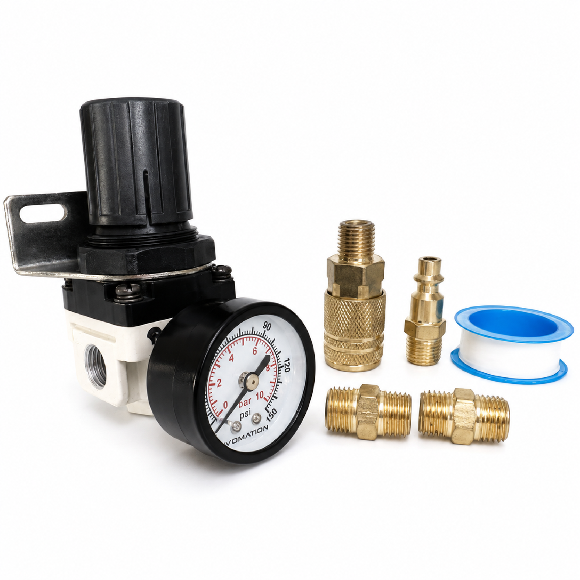
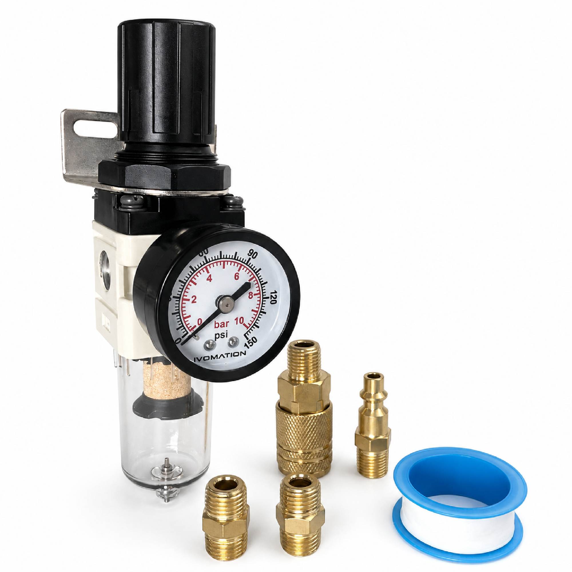
The IVOMATION AW2000 pneumatic filter regulator combines:
Before selecting an AW2000 or another compact filter regulator, confirm:
A compact unit may not be suitable for:
The correct product depends on the complete air system rather than the port size alone. View the IVOMATION AW2000 Pneumatic Filter Regulator
Before ordering a pneumatic filter regulator, confirm the following:
A pneumatic filter regulator removes condensed water and solid particles while reducing compressed air to a controlled downstream pressure. Selecting the right unit requires more than matching a port size. Airflow, thread standard, filtration rating, supply pressure, outlet pressure, drain type, regulator behaviour, bowl construction, and installation conditions all affect product performance. A properly selected and installed filter regulator can help improve equipment stability, reduce contamination-related problems, and provide a more reliable starting point for pneumatic tools and automation systems. Need help selecting a filter regulator? Contact IVOMATION with your equipment type, required airflow, port size, thread standard, compressor pressure, operating pressure, and preferred drain type. Contact IVOMATION